
Technical Note: TN0080 - Rev 01
Below outlines the method of integrating both an older UNO PVI and UNO DM Inverters in parallel with an SP PRO.
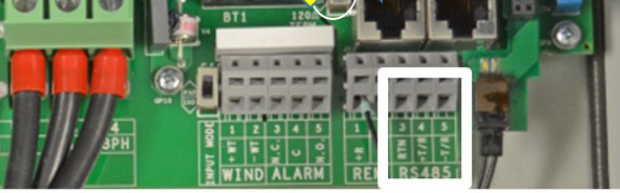
The data cable pinout is different between the ABB UNO PVI units and ABB UNO DM units and a straight through data cable will not work correctly.
UNO PVI RJ45 Pinout | | UNO DM Plus / Plus Q Pinout | ||||
1 | | | | 1 | RTN | Signal Return |
2 | | | | 2 | RTN | Signal Return |
3 | +TR | + Data Line | | 3 | +TR | + Data Line |
4 | +R | Remote Off | | 4 | | |
5 | -TR | - Data Line | | 5 | | |
6 | | | | 6 | -TR | - Data Line |
7 | RTN | Signal Return | | 7 | | |
8 | | | | 8 | | |
PVI and DM in Series (Daisy Chain)
Recommended
- The general idea is to link the signal wiring at the UNO PVI terminals.
- Ensure that the same protocol, whether T-568A or T568-B is used throughout the entire RS485 communications bus for all ABBs.


- PVI units must remain the first units in the RS485 link and subsequent units can be DM PLUS and DM PLUS Q units.
- A non-standard RJ45 to RJ45 cable can be made to allow UNO DM units to connect into the series of PVI units.
- When looping an ABB to another ABB, the termination jumper must be set to “OFF” (away from ON), except for the last ABB UNO only, where the termination jumper must be set to “ON”.
- Alternatively, if you failed to establish communications with a custom RJ45 plug, you can wire directly into the terminals of the UNO PVI, bypassing the RJ45 plugs.
PVI and DM in parallel
Not recommended (Non-standard serial wiring)
- Use the "To other AC Coupled Inverters" middle port on the Interface PCA/Sergio card in SP PRO to connect to ABB Uno DM/any ABB other than a PVI
- Use the "To ABB AC Coupled Inverter" left port on Sergio card to connect to PVIs
- The UNOs will be addressed first sequentially starting at # 2. All PVIs will be addressed sequentially and last.
- 120 ohm termination resistors must be set to ON in last ABB of each string, last PVI and last Uno
- The dip switches at SP PRO comms card next to RS485 Port 2 must be set to OFF
Additional Information:
Visit the Selectronic: Knowledge Base or contact Selectronic via the Customer Portal.